Tech pages · Mods & Builds · Guitar Amps · Tubes · Electronics
Blues Deluxe Mods: A Different Amp Than You Think
I promised this one would just be the Hot Rod Deluxe recipe ported over. Then I actually got the Blues Deluxe schematic out, and it's not the same amp at all.
I owe you a correction before I owe you an article.
At the end of The Ultimate Hot Rod Deluxe Mod I said the same recipe applies to the Blues Deluxe, that it's a similar amp, and that the differences weren't significant enough to matter. Then I actually pulled the Blues Deluxe/DeVille reissue factory schematic to write this piece properly, and I was wrong. These are genuinely different circuits, from different design lineages, and porting one mod list onto the other would send you looking for parts that aren't there and skip real opportunities that are.
So — sorry about that. Here's the amp as it actually is.
The Short Version
- The Blues Deluxe already has a bias trim pot from the factory — R82, set for a documented target at a labeled test point. This is not a "the dreaded resistor mod" situation like the Hot Rod Deluxe; the design problem that mod fixes isn't the same problem here.
- The tone stack is a real FMV-family network with a 250 kΩ treble pot, a 1 MΩ bass pot and a 25 kΩ mid pot — genuinely adjustable and worth understanding on its own terms rather than assuming Hot Rod Deluxe values.
- The presence control is a 25 kΩ pot, likely reverse-taper, wired into the negative feedback path — the same mechanism covered in what the presence knob really does, on a genuinely different value than the Marshalls and Fenders in that article.
- Two 6L6GC output tubes, push-pull, with a documented factory bias procedure: 30 mV per output tube, read at a specific test point with the bias trim pot.
- R78 and R79 exist on this board too, and differ in value between the Deluxe and DeVille assemblies — worth checking on your specific amp, but I don't have evidence this circuit shares the Hot Rod Deluxe's PCB-cooking failure mode, so I'm not carrying that mod over on a guess.
The Amp
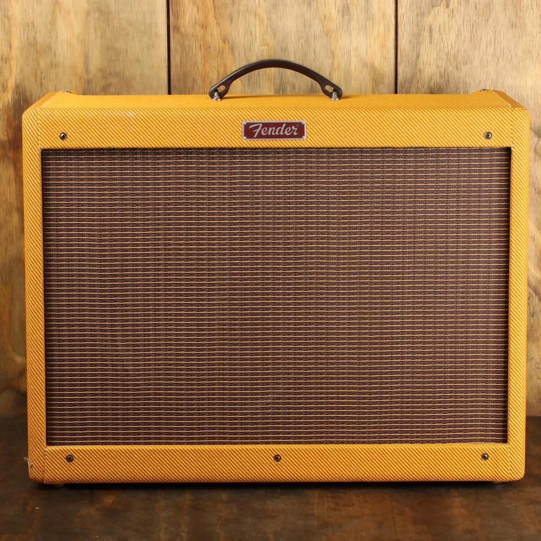
The Blues Deluxe reissue (Fender drawing 0065561000, combined with the 4×10 Blues DeVille on the same sheet set) is a 2×6L6GC, single-channel-plus-drive combo with spring reverb and a factory-fitted bias trim pot. It shares a chassis and PCB family with the Blues DeVille, which is the same circuit driving four 6L6GCs instead of two — most of what's below applies to both, and the schematic itself flags exactly where their component values part ways.
This is not the same design as the Hot Rod Deluxe covered in my other article on that amp. The Hot Rod Deluxe is a later, three-channel PCB design with a documented dropping-resistor heat problem and no factory bias trim. The Blues Deluxe predates it, uses a genuinely different preamp and power-supply layout, and — critically — already has the adjustable bias pot that the Hot Rod Deluxe's whole "resistor mod" exists to compensate for not having. Different amp, different starting problems.
What I Was Going For
Since this is the first pass at this specific amp's schematic rather than a repeat of established client work, the brief here is narrower and more honest than my usual mod logs: confirm what's actually adjustable on this circuit, and flag what would need more bench time before I'd commit to a specific component swap in print.
That's a real distinction worth naming. My mod articles on the Grinder and the Hot Rod Deluxe are jobs I've actually done, repeatedly, on amps in front of me. This is me reading a factory drawing carefully and telling you what it says — useful, traceable, and not the same standard of "I've built this exact mod and played through it," which is a bar I'd rather be honest about not having cleared yet for this specific circuit.
Careful — Read This First
Same rules as every tube amp on this site: B+ on a 6L6GC pair runs comfortably into lethal territory, and the filter caps hold that charge after the amp is unplugged.
- Discharge the filter caps and verify with a meter before opening anything up.
- Never power it up without a speaker or dummy load connected.
- The bias procedure below involves a live amp with the chassis out of the cabinet. Use insulated probes, keep one hand behind your back, and don't do this alone if you're not already comfortable working inside a live chassis.
What's Actually There
The bias trim — already built in
The factory notes on this schematic are explicit: "BIAS ADJUSTMENT — NO SIGNAL APPLIED, RATED LINE VOLTAGE AT T2 POWER TRANSFORMER PRIMARY. SET BIAS ADJUST POT R82 TO OBTAIN A READING OF +60mV AT TP47." A separate note states the target as 30 mV per output tube — the +60 mV figure at TP47 is that same target read across both tubes' shared sense point, not a contradiction.
This is a genuine, adjustable, in-circuit bias trim, using a shunt-style millivolt reading rather than the output-transformer resistance method I generally prefer — worth knowing before you go hunting for an OT centre tap on this particular amp, because the factory procedure here is built around a different measurement point entirely. If you'd rather use the OT-resistance method regardless, nothing stops you — it'll just be a different node than the one Fender's own notes point at.
There is no dropping-resistor heat problem to fix here comparable to the Hot Rod Deluxe's, as far as this schematic shows. That doesn't mean this specific board never runs hot anywhere — it means I don't have evidence of the specific, documented failure mode the Hot Rod Deluxe has, and I'm not going to invent a parallel mod on a guess.
The tone stack — a real FMV network, with its own values
Treble pot: 250 kΩ, with a 250 pF treble cap. Bass pot: 1 MΩ, with a 0.1 µF bass cap. Mid pot: 25 kΩ, with a 0.022 µF mid cap. A 33 kΩ resistor sits ahead of the network in the slope-resistor position.
That's a genuinely different balance from either family in what a tone stack actually does — the 1 MΩ bass pot is enormous compared to the 250 kΩ blackface convention, and the 25 kΩ mid pot puts this stack's potential scoop depth closer to the tweed Bassman/Marshall camp than to the blackface family it visually resembles. Worth loading into Tone Stack Lab before you assume you know what this control set does.
Presence — a genuine feedback-path control
A 25 kΩ pot, marked with a taper code suggesting reverse-audio, sits in the negative feedback path alongside a 4.7 kΩ resistor and a 0.1 µF capacitor. Mechanically this is the same device covered in what the presence knob really does — it's cutting high-frequency feedback, not adding treble — on component values specific to this amp rather than any of the Marshalls or Fenders documented there.
Where the Deluxe and DeVille genuinely differ
The schematic's own notes are explicit that C31, C33, R8, R9, R76, R78, R79, R97 and R102 differ in value between the Blues Deluxe and Blues DeVille PCB assemblies — the same physical board layout, populated differently for the two tube complements. If you're working on one of these amps, that's your instruction to read the values off your own board rather than assume the sibling model's numbers, especially for anything in that list.
What This Means on the Bench
Use the factory bias procedure as written before reaching for anything more elaborate. The trim pot and the documented target voltage are already there; this isn't a "the amp needs a mod to become adjustable" situation.
Don't assume the Hot Rod Deluxe's resistor mod applies here. I said it did, in print, and I was working from a surface-level similarity rather than the actual schematic. Treat that claim as withdrawn until somebody — possibly me, on a future bench session with a real unit in front of me — actually finds and documents the equivalent failure mode on this specific board, if one exists.
If you want a Marshall-adjacent scoop out of this amp, the 25 kΩ mid pot already gives you more room than a blackface-style circuit would. Push the mid control down and compare against what the tone stack article predicts for a 25 kΩ mid pot — it should track closely.
How It Turned Out
This one's unfinished by design. I'd rather publish an honest, schematic-grounded starting point than pad it out with mods I haven't actually put my hands on. When I get a Blues Deluxe on the bench for real work, this article gets a proper "How It Turned Out" section with before-and-after sound and a mod list I've actually verified in the room, not just on paper.
Try It Yourself
Load the tone-stack values above — 33k slope, 250pF treble cap, 250k treble pot, 0.1µF bass cap, 1M bass pot, 0.022µF mid cap, 25k mid pot — into Tone Stack Lab and compare the curve against the Bassman and blackface presets discussed in what a tone stack actually does. For the presence and feedback side, Feedback Lab covers the mechanism this amp's 25 kΩ presence pot is built on.
Sources
- All component values, the bias procedure (R82, target +60 mV at TP47, 30 mV per output tube) and the Deluxe/DeVille value-difference list (C31, C33, R8, R9, R76, R78, R79, R97, R102) are read directly from Fender's factory combined service diagram, drawing 0065561000 Rev A, "Blues Deluxe/DeVille Reissue," release 2004-12-14.
- This schematic covers the reissue circuit (PCB assemblies 0065560000 / 0065572000 Deluxe, 0065559000 fabrication). An original-era Blues Deluxe from the 1990s may differ; verify against your own amp's revision before cutting anything.
- The presence pot's taper is marked with a code on the drawing consistent with a reverse-audio (C) taper; I have not independently confirmed this against a physical unit.