Tech pages · Effect Pedals · Electronics · Measurement
Building Better Pedals: The Real Role of Components in Guitar Tone
Which parts in a pedal actually change the sound, which only change the price, and the one question — where is this component sitting? — that tells you which is which.
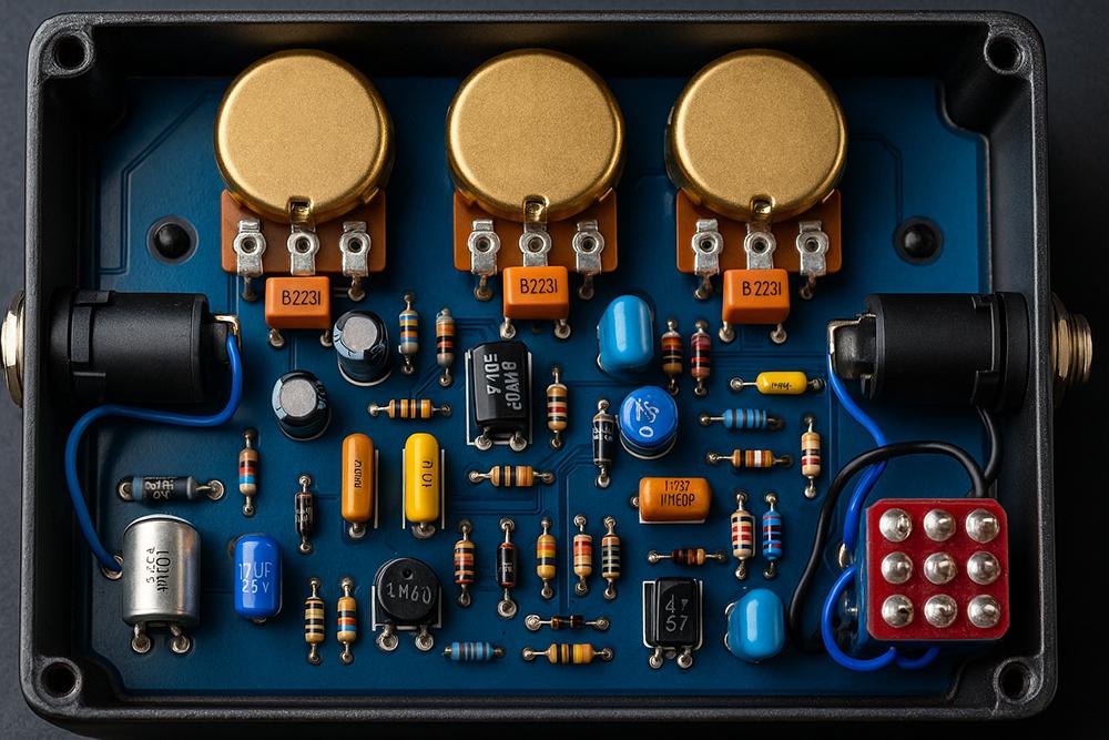

One question keeps coming back, from players, builders and people trying to justify a purchase: does component quality actually change how a pedal sounds?
The marketing answer is obvious — audiophile-grade parts, vintage reissues, exotic dielectrics. The forum answer is usually the opposite: it is all placebo, buy the cheap ones. Both are wrong, and they are wrong in the same way. They are arguing about the part when the answer depends almost entirely on where in the circuit the part is sitting.
So rather than a shopping list, here is a way of thinking about it, followed by an honest survey of everything you will find inside a stompbox.
The Short Version
- Ask one question about any component: is it in the signal path, is it setting a DC operating point, or is it in the power supply? That single distinction predicts almost everything.
- Signal path — capacitors in filters and coupling, clipping diodes. Value matters a lot. Type matters some. Brand almost never.
- Bias setting — resistors that set where a transistor idles. Tolerance matters more here than anywhere else, because a shifted operating point changes clipping symmetry, which is genuinely audible.
- Power supply — filter caps, dropping resistors. Matters for noise and reliability, essentially nothing for tone, unless the circuit has no decoupling at all.
- Tolerance arithmetic settles most arguments. A 5 % error on a filter capacitor moves a corner frequency by less than a semitone — inaudible. A 20 % error on a bias resistor can move an operating point far enough to hear.
- The genuine exceptions exist and are worth knowing. The Rat's LM308 op-amp is slow on purpose, and swapping it for a "better" chip removes a defining part of the sound.
What Everyone Gets Wrong
The mistake is treating "component quality" as one axis, running from cheap to good, with tone somewhere along it.
It is not one axis. A component in a pedal is doing one of three jobs, and its job determines what about it matters:
In the signal path. A coupling capacitor, a filter capacitor, a clipping diode. The audio itself goes through it. Its value sets a frequency or a threshold and is a genuine design decision. Its type matters for second-order reasons — dielectric absorption, voltage coefficient, parasitic inductance. Its brand essentially never matters, and the difference between two brands of the same type is far smaller than the difference between two adjacent standard values.
Setting a DC operating point. A collector resistor, an emitter resistor, a bias divider. No audio passes through it in any meaningful sense — it decides where the transistor idles. And this is the one place where tolerance genuinely matters a great deal, because a moved operating point changes how the stage clips, and clipping asymmetry is directly audible as harmonic content.
In the power supply. A filter capacitor, a dropping resistor. Matters for noise, for hum, and for reliability. For tone: nothing — unless the circuit is one of the minimally decoupled vintage designs where the supply is part of the signal path, which is exactly why the fuzz crowd argues about power and the overdrive crowd does not.
The tolerance arithmetic
Here is the calculation that settles most of the boutique-parts argument.
Take a filter formed by a resistor and a capacitor. Its corner frequency is:
Now suppose the capacitor is 5 % off nominal. The corner moves by 5 %. In musical terms, a 5 % frequency shift is:
Under a semitone, on a broad first-order filter with a 6 dB/octave slope. You will not hear that. Even a 10 % part gives you about 165 cents on a gentle shelf — audible in a careful A/B, invisible in a mix.
Now put that same 10 % error on the emitter resistor setting a fuzz transistor's operating point. The collector voltage moves, the available headroom on one side of the waveform moves with it, and the clipping goes asymmetric — which adds a whole family of even harmonics that were not there before. That you hear immediately.
Rule of thumb: Buy 1 % parts where they set bias. Buy whatever is in the drawer where they set a corner frequency. And stop reading capacitor reviews.
Resistors
Resistors define voltage relationships, limit current, set bias conditions, and — through interaction with capacitors and nonlinear elements — contribute to tone shaping. Their direct impact on tone is routinely overstated. Their impact via bias is routinely understated.
Carbon composition

Widely used in vintage audio and guitar circuits, valued at the time for being available rather than for being good. High thermal noise, broad tolerance (often ±10 % to ±20 %), and poor long-term stability — they drift with age and humidity.
In some vintage fuzz circuits their slight nonlinearity and voltage-dependent behaviour do contribute a characteristic saturation. This is real and it is also thoroughly exaggerated in pedal lore. Note the more interesting consequence: with ±20 % tolerance setting bias points, no two vintage fuzzes were ever the same circuit. That variation is a large part of what people are actually hearing when they say vintage units have character.
- Applications: classic fuzz, vintage reissues
- Performance: noisy, unstable, wide tolerance
- Cost: significantly more expensive than modern types, purely through rarity
Carbon film
Cost-effective and reliable, with better noise performance and tighter tolerance (typically ±5 %). Standard in budget and mid-tier pedals, fine in both signal and power paths.
Metal film
Excellent precision (typically ±1 %), very low noise, high thermal stability. The right default for almost everything, and specifically the right choice anywhere a bias point is being set. Some builders avoid them in vintage-style fuzz circuits for lacking "coloration," which — see the tolerance discussion — mostly means lacking randomness.
Metal oxide
Like metal film but built for higher power dissipation. Electrically robust, physically large, often too big for a compact layout. Best in power supply sections where heat is the concern.
Wirewound
Excellent thermal handling and very high power ratings, but significantly inductive and physically large. That inductance is disqualifying in a signal path. Reserved for amplifiers, power attenuators and load boxes rather than stompboxes.
Foil resistors

Ultra-precision parts for lab-grade and audiophile equipment: extremely low thermal drift, tolerances of ±0.1 % or better. They are excellent, they are expensive, and there is no application in a guitar pedal where their advantage over a 1 % metal film would be measurable, let alone audible.
Surface-mount (SMD)
The standard for modern manufacturing, and — despite the scepticism — generally better than through-hole equivalents. Compact, reliable, electrically consistent, with lower parasitic inductance precisely because the leads are gone. Their only real limitation is power handling, which is a function of size.
Specialised types
- Thermistors — used for thermal stabilisation in power supplies, and to compensate for temperature drift in germanium circuits. Genuinely useful in a Fuzz Face that changes character with room temperature.
- LDRs (light-dependent resistors) — integral to optical tremolos, phasers and compressors. They have become hard to source, especially the ones that suit vintage circuits, are relatively expensive, and are prone to long-term failure — Vactrols especially. Despite that, many iconic circuits depend on their particular response to light, which is not a linear one and is a real part of how those effects breathe.
Capacitors

Capacitors define filter characteristics, block DC while passing AC, and stabilise power rails. Unlike resistors, a capacitor's value in a signal path has a direct and audible effect on tone — that is its whole job.
Electrolytic
Polarised, high capacitance in a small package, cheap. The staple for power supply filtering and for coupling where a large value is needed.
They also age: the electrolyte dries, ESR climbs and the value drifts. Worth being precise about their reputation in the signal path — the usual claim is that they are simply bad for audio, and that is not quite it. They distort when there is insufficient DC bias across them, because the dielectric is formed electrochemically and needs a polarising voltage to behave. Properly biased with adequate voltage across them, they are used in coupling positions in enormous numbers of perfectly good circuits. Used with near-zero DC across them, they are genuinely poor.
Tantalum
Smaller and more stable than aluminium electrolytics, with lower ESR and better consistency over temperature.
One correction to the usual boutique framing: tantalums are still polarised electrolytics with their own nonlinearity, and they are not a distortion improvement over a film capacitor in the signal path. Their advantages are size, stability and ESR — not linearity. They also fail short-circuit and sometimes spectacularly when over-voltaged or reverse-biased, which is the real reason they are uncommon in pedals.
Ceramic
Widely used for bypassing, filtering and frequency shaping, and their behaviour varies enormously by dielectric:
- Class I (C0G / NP0) — stable, low-loss, low-distortion, and the correct choice for any small-value signal-path capacitor. Limited to small values.
- Class II and above (X7R, Y5V and friends) — capacitance shifts substantially with applied voltage and temperature. A Y5V part can lose most of its nominal value at rated voltage. Fine for decoupling, poor for anything setting a frequency you care about.
That voltage coefficient is the actual, measurable mechanism behind "ceramics sound bad in the signal path." It is not mojo, and it does not apply to C0G at all.
Film

The standard for signal handling: stable capacitance, low distortion, tight tolerances, no voltage coefficient worth mentioning. Builders prefer them for coupling and filter networks and they are right to. Audio-grade types (WIMA, Panasonic ECQ and similar) are good parts at sane prices; the trade-off is size, which is why compact production pedals use ceramics.
Silver mica
Precise and extremely stable, used in high-frequency and high-fidelity circuits. Mechanically fragile and physically large for their capacitance, which keeps them rare in pedals — though they turn up in boutique EQ stages, where they are a reasonable if unnecessary choice.
Surface-mount

Standard in modern manufacturing, and electrically they perform as well as or better than through-hole equivalents — the shorter leads mean less parasitic inductance. The dielectric class question above still applies and matters more than the package: an SMD C0G is an excellent signal capacitor, an SMD Y5V is not.
Diodes

Diodes are what make most overdrive and distortion pedals work. Their job is clipping — limiting the signal voltage by conducting above a threshold — and the parameter that decides everything is forward voltage, .
But be clear about the mechanism: the diode does not have a sound. It has a forward voltage and a recovery time, and those change the clipping threshold and the softness of the transition. Everything else is the circuit around it. Two silicon diodes with identical specs may vary microscopically; that variation is not what you are hearing.
One correction to a very common claim: symmetry is a property of the arrangement, not of the diode type. Two matched diodes back to back give you symmetrical clipping regardless of what they are made of. Two one way and one the other gives you asymmetrical clipping, again regardless of type.
Silicon
Most overdrives and distortions use ordinary silicon — the 1N4148 above all. Forward voltage around 0.7 V, giving a relatively hard clip and the classic tight, compressed distortion.
- Character: bright, crisp, aggressive
- Use: most classic and modern distortion
Germanium

Types like the 1N34A have a much lower forward voltage, around 0.3 V, so they clip earlier and more softly. The result gets described as vintage or organic, and the softer knee is a real, measurable thing rather than a story.
The downsides are also real: germanium is temperature sensitive and inconsistent, and genuinely hard to source. Forward voltage varies noticeably part to part, which produces audible differences between supposedly identical pedals — sometimes celebrated as character, sometimes just a defect.
LEDs
An LED is a diode with a much higher forward voltage, and its colour tells you the voltage — roughly 1.8–2.0 V for red, around 2.1 V for green, and 3 V or more for blue and white. That range is wide, and it is a real design lever.
Because the clipping threshold is so much higher, an LED lets far more signal through before it acts. The result is less compression and more dynamic range — a more amp-like distortion that keeps your picking dynamics rather than flattening them.
- Character: open, bold, dynamic
- Use: amp-emulating overdrives, looser gain stages
- Note: colour sets threshold; red clips earliest, blue and white latest
Schottky

Very low forward voltage, around 0.2 V at small signal currents, giving very soft, early clipping and a compressed feel. Their fast switching and low drop also make them the standard choice for input protection against voltage spikes, which is a job they do far more often than clipping.
Zener
A zener conducts at its ordinary forward voltage in one direction and at its much higher zener voltage in the other — which makes a single zener an asymmetric clipper by construction. That is a genuinely elegant trick, and low-voltage zeners (under about 5 V) are the useful ones for audio.
Transistors as diodes
Both BJTs and MOSFETs can be wired in diode-like configurations for clipping, and the result is usually softer and more gradual than a plain diode array — a MOSFET's channel does not switch on as abruptly as a junction does. It shows up in several boutique and amp-in-a-box circuits for exactly that reason.
Transistors

Transistors are the amplifiers, gain stages, buffers and active tone-shapers. They determine gain, response and distortion behaviour more directly than any passive part.
The specifications that matter are hFE (DC current gain), noise, device type, and — far more than any of them — how the transistor is biased. A "high-quality" transistor will not improve tone on its own. Circuit design and biasing dominate.
Bipolar junction transistors

BJTs — 2N3904, 2N5088 and their many relatives — are the most common type in classic pedal circuits, in NPN or PNP polarity, in everything from fuzz to boost.
Vintage BJTs generally had lower hFE than modern equivalents. As manufacturing improved, parts became more consistent and higher gain, which is why dropping a modern substitute into an old circuit often sounds brighter, more aggressive or harsher: the bias point moved and nobody adjusted for it. The transistor is not "wrong." The circuit around it is now wrong for it.
Matching by hFE matters in phase shifters, octave fuzzes and multi-stage gain sections. But hFE alone is not the whole story — two transistors with identical hFE can behave and sound different because of leakage current, base-emitter voltage and other parameters. A curve tracer shows you the whole picture across bias points, which is exactly why it is the right tool and exactly why almost nobody has one.
Germanium
Common in the 1960s and prized in certain fuzz circuits for a warm, compressed, saggy character. Typically low hFE and extremely temperature sensitive — which is the source of both their instability and their appeal.
The practical problems are severe: performance varies dramatically unit to unit, leakage current is significant and drifts with temperature, and genuine working parts are hard to find. Properly selected and biased, they do produce a distortion that is difficult to imitate with silicon. Poorly selected, they produce a pedal that works differently in the afternoon than it did in the morning.
Silicon
High gain, stability, consistency. The default for nearly all modern analogue pedals. Often described as brighter or harsher than germanium, but the real outcome depends on how the circuit is biased and voiced — a silicon Fuzz Face biased properly is not a harsh pedal.
JFETs
JFETs get compared to tubes constantly, and unlike most such comparisons this one has a real basis. A JFET's transfer characteristic — drain current against gate voltage — follows an approximately square law, which is close to the shape of a triode's characteristic and quite different from a BJT's exponential one. That shape is what produces the smoother onset of nonlinearity and the touch-sensitive response people describe.
The catch is that JFETs vary enormously part to part. Pinch-off voltage and can differ by a factor of two or three within the same part number, which means most serious JFET designs require individually biasing each device by trimming the source or drain resistor. That is real labour, and it is why JFET pedals cost what they cost.
MOSFETs

Mostly used as clippers, or as part of hybrid gain stages, producing a crunchy amp-like distortion — the mainstay of a lot of amp-in-a-box designs.
They can be used as gain stages, but they are not naturally suited to it: their transconductance at the small currents a 9 V pedal runs is low, so you get less gain per stage than a BJT gives you, and they can sound spiky if implemented carelessly. With proper filtering and voicing they add real edge and character.
A note on fakes and mil-spec
Military-spec transistors offer better temperature and voltage tolerance. In a pedal on a stage, the benefit is negligible.
Fake or mislabelled transistors are common on secondary markets, especially for sought-after vintage types. They can drastically alter a circuit's behaviour, and they should be tested rather than trusted. If you are paying vintage prices for germanium, measure hFE and leakage before you solder.
ICs and Op-Amps

Op-amps are the brains of many overdrive, distortion and modulation pedals — gain stages, buffers, filters and oscillators in one small package.
They have real, measurable characteristics: slew rate, input offset voltage, noise floor, bandwidth, output drive. And in most pedal circuits the tonal differences between models are vastly overstated, because a pedal's gain, filtering and clipping are all set by the parts around the chip.
Most, but not all. Which brings us to the exception worth knowing.
The exception that proves the rule: the Rat
The ProCo Rat uses an LM308, an op-amp with a notoriously low slew rate. At high gain the chip physically cannot keep up with fast transients, and that limitation shapes the attack of every note. It is not a flaw that got tolerated; it is a defining part of what a Rat sounds like, and swapping in a "better," faster op-amp measurably improves the specifications and removes the character.
That is what a genuine op-amp difference looks like: a specific parameter, at a specific limit, doing something audible. If somebody cannot name the parameter, there probably isn't one.
Common pedal op-amps
Most pedals use cost-effective, well-understood chips — the JRC4558, the TL072, the NE5532. Reasonable noise, adequate headroom on a 9 V rail, easy to buy.
The Tube Screamer's JRC4558D is the famous one, and the mojo around it is mostly manufactured. Differences between variants can be heard in a careful A/B in the same circuit, and they are not dramatic. What matters far more is that the pedal was designed around the chip and its 9 V headroom limits, which is a design achievement rather than a component one.
"Audiophile" op-amps

High-performance parts like the OPA2134, LT1357 or AD712 offer low distortion, wide bandwidth and low noise. In a 9 V pedal those characteristics are often underutilised, and occasionally counterproductive — in a circuit whose job is harmonic colouration, a chip that refuses to contribute anything can genuinely sound sterile.
Worth checking before you swap: many high-performance op-amps expect a dual supply and more headroom than a single 9 V rail gives them, and some draw substantially more current than the original. "Better on paper" and "drop-in replacement" are different claims.
Bucket brigade devices

Analogue delay, chorus and flanger pedals depend on bucket brigade devices — chips that delay an analogue signal by passing a charge down a long chain of capacitors and MOS switches, one clock step at a time. No conversion to digital, which is why they sound the way they do, and also why they are noisy and limited in headroom.
The legendary parts — MN3005, MN3207 — are long out of production and expensive. Modern reproductions from Coolaudio are generally excellent alternatives, though plenty of low-quality copies exist and consistency varies.
BBDs are a major cost driver in analogue modulation pedals, and they are most of the reason an analogue delay costs several times what a digital one does.
Fakes, packages and supplies
Fake or relabelled op-amps are increasingly common, especially for vintage or discontinued parts like the JRC4558D and legacy delay chips. They usually work; they often do not meet the noise or consistency spec. Buy from real distributors.
Supply voltage genuinely matters. An op-amp on 18 V has twice the headroom it has on 9 V, and in a clipping circuit that changes where the clipping happens and what is doing it. This is a real mod, not a placebo.
DIP versus SMD makes no electrical difference used correctly. DIP is better for prototyping and modding; SMD is better for manufacturing and much harder to swap.
The Unsung Parts
Inductors

Rare in pedals but central to a few — wah filters, some EQs, certain modulation circuits. An inductor stores energy in a magnetic field and forms the resonant element of a wah's filter, and its inductance sets where that filter sweeps.
The mojo reputation is largely undeserved. It is wire wound around a core, and its inductance and DC resistance are the specifications that matter. Both affect where the peak sits and how sharp it is, which is a real effect — but the gritty character people attribute to vintage wah inductors mostly comes from the active stages around them.
Wire
Silver-plated or oxygen-free copper wire will not transform your tone. Inside a pedal the wire lengths are far too short for anything else to be true.
What wire can do is introduce noise, if it is routed badly or if a high-impedance section is unshielded. Good solder joints, solid mechanical connections and sensible layout contribute more to how a pedal performs over ten years than any boutique wire claim.
Potentiometers

Pots control volume, gain and tone, and their mechanical reliability and electrical consistency matter to both sound and usability. Bad pots give you scratchy noise, uneven sweeps and early failure.
Two things worth knowing:
Modern PCB-mount pots are generally better than vintage-style solder-lug ones. Many of the classic types are no longer built to the standard they once were, while 16 mm and 24 mm PCB-mount parts offer better build quality, tighter tolerances and longer life. That said, old pots are often fixable — cleaning and re-lubricating brings a scratchy control back to life more often than people expect.
Pot tolerance is wide — commonly ±20 %, sometimes worse. A pot labelled 100 kΩ can measure a very long way from 100 kΩ. In a circuit where a pot sets a filter's impedance or a gain range, that variation produces genuinely noticeable differences between otherwise identical pedals. This is one of the real, unglamorous reasons two units off the same production line do not sound the same.
Taper matters as much as value. A linear pot where the circuit wanted an audio taper makes a control that does everything in the first quarter of its travel. That is a usability disaster and it has nothing to do with tone.
Switches, jacks and connectors
Footswitches, input and output jacks, DC power jacks. They contribute nothing to tone and everything to whether the pedal works in two years.
Poor jacks oxidise and loosen, giving intermittent signal loss. Footswitches with mechanical bounce or inconsistent action cause bypass glitches, which are particularly visible in true-bypass designs. Buy good ones. This is the one category where paying more is straightforwardly correct.
Enclosures and shielding

Not an electronic component, but the enclosure does real work: EMI shielding, thermal stability and mechanical durability. A grounded aluminium box meaningfully reduces radio interference and hum, which matters most in exactly the high-gain designs most likely to pick it up.
Watch the grounding. Powder coating and internal paint are insulators, and a pedal whose jacks are supposed to ground through the chassis will not do so through a coat of paint. Scrape the contact points.
What This Means on the Bench
Component quality matters — but almost never in the direction the marketing points.
A well-designed circuit sounds excellent with inexpensive, reliable parts. A poorly executed one underperforms with the most expensive components available. The interaction between parts, how they are biased and how the circuit is voiced dominate anything a single component contributes.
So when you are building or modifying, spend your attention here:
- Circuit design and topology first. Nothing else comes close.
- Tolerance where it sets bias. 1 % metal film on every resistor that decides where a transistor idles. This is cheap and it is the highest-value upgrade on this page.
- Dielectric class where it sets frequency. C0G or film in the signal path, not Y5V. Also cheap.
- Mechanical quality on the parts that move. Jacks, switches, pots. This is where a pedal actually dies.
- And measure the transistors if the circuit depends on them — germanium especially. Selection beats sourcing.
Exotic parts occasionally add nuance. They are never a substitute for thinking about the circuit.
Try It Yourself
The bias argument that runs through this whole article — that where a device idles matters more than what the device is — is exactly what FET Playground was built to make obvious. Measure a real JFET, design a stage around that specific part, then move the source resistor and watch the operating point slide and the transfer curve go asymmetric under you. Ten minutes with that will do more for your instincts than any amount of reading about component brands, including this.
For the filter side, Tone Stack Lab shows you what changing a capacitor value does, which is the effect people usually attribute to changing a capacitor type.
Sources
- Forward voltage figures are datasheet typicals at small-signal currents: 1N4148 silicon ≈ 0.7 V, 1N34A germanium ≈ 0.3 V, Schottky ≈ 0.2 V, LEDs from ≈ 1.8 V (red) to over 3 V (blue/white). Real parts vary, germanium most of all.
- Ceramic dielectric classes and their voltage/temperature coefficients follow the EIA classification. The Class II voltage coefficient is published by every major manufacturer and is larger than most people expect.
- The ProCo Rat's use of the LM308 and that chip's slew-rate limitation is documented in the circuit's published schematics and the part's datasheet.
- The tolerance-to-cents conversion is .
- Component tolerance ranges (±1 % metal film, ±5 % carbon film, ±10–20 % carbon composition, ±20 % typical for pots) are standard manufacturer specifications.
- Where I have described a part as sounding a particular way, that is my own opinion from the bench and should be read as such. Where I have given a number, it comes from a datasheet.
Whether you are chasing vintage mojo, boutique tone or just a solid build: it is not about the price of the parts. It is about knowing which of them is doing the work.