Tech pages · Pickups · Electronics · Measurement
The Pickup Equation: Resistance, Inductance, and Capacitance Demystified
DC resistance is the one number every shop lists and the one that tells you least. Here is what actually decides how a pickup sounds — and the equation that ties it together.
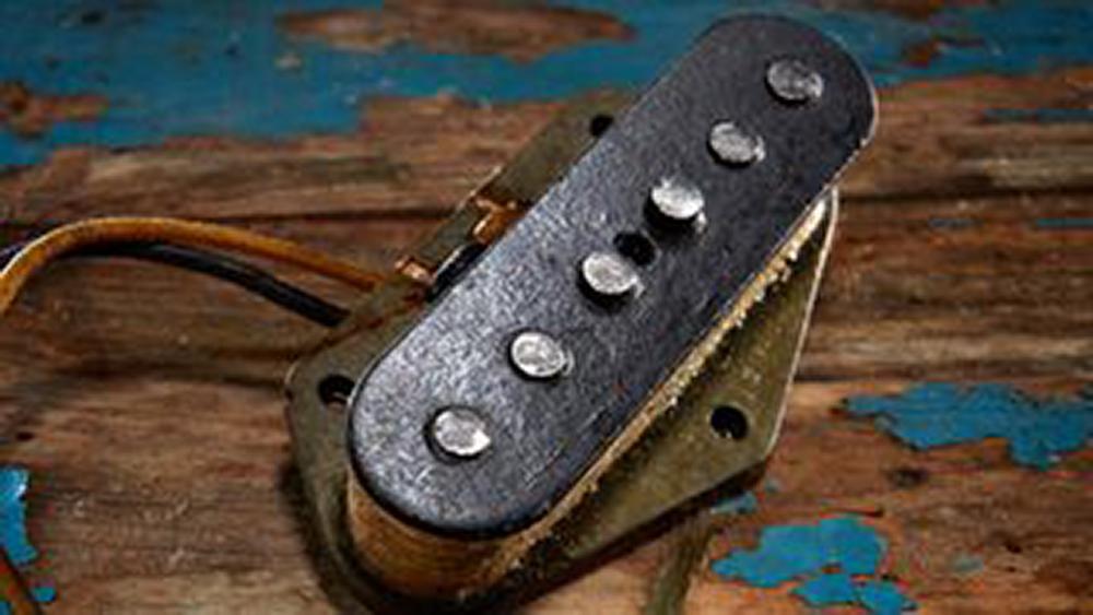
Go and look at any online shop selling guitar pickups. Dozens of models, and for almost all of them you will get exactly two pieces of information: the DC resistance, and the magnet type.
That is not an accident, and it is not laziness. It is the number that is cheapest to measure — anybody with a ten-euro multimeter can check it — and it happens to be the number that tells you least about how the pickup will sound. The industry has been quietly happy about that arrangement for about seventy years, because a specification nobody can interpret is a specification you can build marketing on.
So this is the introduction to pickups I wish somebody had handed me. What the parts are, which measurements matter, and — since the article is called The Pickup Equation — the actual equation that ties them together.
The Short Version
- DC resistance is not output. It tells you how much wire is on the bobbin, which correlates with output only if everything else is held constant, and everything else never is.
- Inductance is the number that matters most. It, together with capacitance, sets the resonant peak, and the resonant peak is most of what you hear as bright or dark.
- The equation is the ordinary resonance formula: . For a typical Tele bridge pickup on a 5 m cable, that lands around 2.9 kHz.
- Most of the capacitance in that formula is your cable, not your pickup. A 5 m lead adds 400–600 pF against the pickup's own 200–250 pF.
- More turns of wire raises output and inductance and resistance together. You cannot make a pickup hotter without also making it darker — unless you change the magnet instead.
What Everyone Gets Wrong
There are two ways of looking at guitar pickups, and both are correct.
From one side they are simple, crude devices — a coil of wire near a magnet, poorly engineered by any modern standard. From the other they are extraordinarily sensitive, where every detail makes a difference and micro-changes measurably alter how you feel about playing.
What matters is holding both ideas at once: everything makes a difference, and some things make a much bigger difference than others. This article is about the second half of that sentence, because that is the part that saves you money.
How the thing actually works
A magnetic guitar pickup is a system of four parts, not one:
- The permanent magnet, which creates the magnetic field.
- The magnetic field itself, which extends out past the pickup.
- The coil windings, which generate a voltage when that field changes.
- The strings, which are magnetic, sit inside the field, and become part of the magnetic circuit.
When a string vibrates it disturbs the field. The field strength at the coil fluctuates in step with the string's position, and a changing magnetic field through a coil induces a voltage across it. That is the entire mechanism.
Two consequences fall straight out of it, and both explain things players find mysterious:
The field is leaky. It is not neatly aimed at the strings; it spills out in every direction, which means anything else with a changing magnetic field nearby — mains wiring, transformers, dimmers, screens — induces a voltage in the coil too. That is your hum, and it is not a manufacturing defect. It is the price of the mechanism.
The field is shaped by whatever is near it. Put ferrous material in it and the field bends. That is why a Telecaster bridge pickup's base plate changes its voice, and why the material of a mounting screw is not a placebo.
The misconception the industry built a business on
Which brings us to the DC resistance problem.
Resistance is determined by exactly two things: the thickness of the wire and its length. Thinner wire has more resistance per metre; longer wire has more resistance. That is all.
Now, more turns of wire means a longer wire, so more turns does raise resistance. And more turns also raises output. So resistance and output do move together — when nothing else changes.
But something else always changes. Here are two pickups that demolish the shortcut:
- Seymour Duncan SH-1 '59, bridge: Alnico 5, about 8.2 kΩ. A vintage-output PAF voice.
- Seymour Duncan SH-4 JB: Alnico 5, about 16.4 kΩ. Twice the resistance.
Same magnet type, same manufacturer, same basic format. The JB is indeed hotter — and it is also noticeably darker and thicker, because all those extra turns raised the inductance right along with the output. That is not a coincidence; it is the mechanism. You will meet it again in a moment.
The Physics You Actually Need

Magnets, briefly
The famous ones are AlNiCo — an alloy of aluminium, nickel and cobalt — graded by composition into types. Alnico II and Alnico V are the two you meet constantly, and the usual shorthand is that V is "hotter" than II. That is roughly right: Alnico V is a different alloy composition, produces a stronger field, pulls harder on the strings and yields a higher output voltage for the same coil.
Two things worth knowing beyond that. Grades vary between suppliers — one maker's Alnico V is not identical to another's, and sometimes by more than you would expect. And ceramic and neodymium are also in common use, each with its own field characteristics.
The key point is the one that sets up everything below:
The output voltage of a pickup is set by the strength of the magnetic field and the number of coil turns.
Two variables, one result. Which means you can trade one against the other — and that trade is where pickup design actually lives.
The coil
The coil is simple to describe and hard to do well. Wire is wound around a bobbin, with a magnet or a ferromagnetic slug at the centre.
More turns means more induction, so more output. But you cannot add turns forever: the bobbin has finite space. So when a designer wants more turns, they reach for thinner wire — which has more resistance per metre. Wire gauge, turn count and coil geometry all end up shoving each other around, and that is the game.
The three measurable quantities
DC resistance. Covered above. Wire thickness and wire length, nothing else. Easy to measure, weakest predictor.
Inductance. The one that matters, and the one nobody lists. Think of it as a measure of the coil's efficiency at converting field change into voltage. It depends on:
- The number of turns (more turns, higher inductance — and it scales with the square of turns, not linearly)
- The core material — magnet, steel slug, or air
- The shape and size of the coil
Measuring it properly needs an LCR meter rather than a multimeter, which is most of why the industry doesn't quote it.
Here is a detail that surprises people: tighter, more precise winding gives you slightly higher inductance than scatter winding, because the turns sit closer to the core on average. Which raises the obvious question — if precise winding is more efficient, why do we prefer hand-wound coils with plenty of scatter? Hold that thought.
Capacitance. Any two conductors separated by an insulator form a capacitor, and a pickup coil is thousands of turns of insulated wire lying on top of each other. It is set by:
- Insulation thickness, which follows from the wire type — Heavy Formvar, Plain Enamel and so on.
- Winding quality. More scatter means turns sit further apart on average, which means less capacitance.

And there is the answer to the scatter-winding question. Scatter winding lowers capacitance while barely touching inductance, which pushes the resonant peak up and opens the pickup out. A perfectly machine-wound coil is more efficient and duller. "Imperfect" turned out to be a feature, and it took the industry decades to admit it.
The rest of the guitar is part of the pickup
This is the piece people leave out, and it changes everything.
A pickup never works alone. Between the coil and the first gain stage of your amp sits a whole passive network: the volume pot, the tone pot and its capacitor, any treble bleed, the switch, the jack, and — most importantly — the cable.
Passive networks are lossy. This one loads the pickup down, moves its resonant peak and eats bandwidth. Which is why I take all my measurements as part of the complete circuit. Honestly, I don't care how a pickup sounds on its own. I need to know how it sounds in my guitar, through my cable.
The cable in particular deserves more respect than it gets. A 5 m instrument lead contributes somewhere around 400–600 pF depending on brand, and that is several times the pickup's own internal capacitance. Change your cable and you have changed your pickup's resonant frequency. That is not audiophile nonsense; it is the arithmetic below.
Running the Numbers
Here, at last, is the pickup equation. It is not exotic — it is the standard resonance formula, which is exactly the point:
The coil's inductance and the total circuit capacitance form a resonant circuit, and that resonance produces a peak in the frequency response. Where that peak sits is most of what you perceive as the pickup's voice.
Let's put real numbers in. A typical Tele-type bridge pickup:
with two 250 kΩ pots wide open and a 5 m cable adding, say, 500 pF. Total capacitance is 750 pF:
Right in the middle of where the ear is most sensitive, which is not a coincidence — it is why electric guitars cut through.

Each line in Figure 3 changes exactly one parameter. In reality you cannot raise inductance without touching resistance — these are deliberately artificial, to isolate what each one does.
Green is the reference, the values above, peaking near 2.9 kHz.
Blue raises resistance to 16 kΩ and leaves everything else alone. Notice how little moves. The peak stays exactly where it was — resistance is not in the resonance equation at all. What it does is damp the peak, smoothing it out, and cost a little output. This one plot is the entire case against shopping by DC resistance.
Dark yellow raises capacitance to 800 pF, so with the cable we are at 1300 pF and the peak drops to about 2.2 kHz. High end goes, and the peak's shape changes with it — which in practice reads as "quacky." You have heard this before, because it is exactly what a longer cable or a rolled-back tone control does.
Red and pink move the inductance, and this is where the plot gets dramatic. Red is 10 H, dropping the peak to about 1.8 kHz — dark and thick. Pink is 2 H, lifting it to about 4.1 kHz — bright and open. Nothing else in the circuit produces swings that big.
The sound of a pickup is dominated by its inductance.
Now put that together with what we established earlier: winding more turns raises output, resistance and inductance simultaneously. So:
Rule of thumb: You cannot wind a pickup hotter without also winding it darker. A hotter pickup is a darker pickup, unless you change the magnet instead of the turn count.
Which is the whole design trade, stated in one line. Want more output without losing the top end? Use a stronger magnet and keep — or reduce — the turns. That is precisely what the high-output pickup designers have been doing since the DiMarzio Super Distortion, and every one of them found a slightly different balance.
That balance can also be pushed too far. PRS's 513 pickups were an exercise in maximum efficiency: a special coil shape, special magnet geometry, and the wire brought as close to the magnet as possible. Efficient means inductive. The result was, to my ears, too dark, with a resonance down around 1.5 kHz that made it distinctly nasal. Entirely subjective, and I am sure it worked beautifully for somebody — but it is a nice illustration that "more efficient" is not the same as "better."
What This Means on the Bench
Compare like with like. Pickup position makes an enormous difference, so comparing two pickups in different positions on different guitars tells you nothing. Neither does comparing an Alnico V Tele bridge to an Alnico V P90 — the coil geometry is a bigger variable than the magnet.
Read the resistance as a turns count, not an output figure. High DC resistance means a lot of wire, thin wire, or both. Treat it as evidence about construction, then ask what that construction does to inductance.
If you want darker and smoother, go Alnico II. The weaker magnet means the winder needed more turns for a comparable output, which raises inductance, which lowers the resonance. If you want punchier and more open, go Alnico V with a lower turn count. That is a generalisation, but it is the right generalisation.
Change your cable before you change your pickup. It is the cheapest experiment on this page, it moves the resonant peak measurably, and it costs a fraction of a rewind.
Try It Yourself
Take the resistance measurement you already trust and put it next to an inductance figure. If you can borrow an LCR meter for an afternoon, measure every pickup you own at 1 kHz and write the numbers down. You will very quickly stop believing the shop listings.
For seeing the effect rather than calculating it, Tone Stack Lab is the closest tool I have. It is a different network — an amp's tone stack rather than a pickup — but it is the same physics made visible: change one component, watch a resonance move. That intuition transfers directly.
There is no dedicated pickup tool yet. It is on the list, and this article and Pickup Coils in Parallel are the two reasons why. Read that one next — it takes these same three quantities and shows what happens when you rewire a humbucker to change all of them at once.
Sources
- Seymour Duncan published specifications for the SH-1 '59 (bridge, ~8.2 kΩ) and SH-4 JB (~16.4 kΩ), both Alnico 5.
- Component values used in the worked example (4 H, 8 kΩ, 250 pF) are representative of a Telecaster-type bridge pickup, chosen to make the arithmetic clean. Measure your own.
- Cable capacitance of 400–600 pF per 5 m is the usual published range for common instrument cable. It varies by nearly a factor of two between brands.
- The PRS 513 assessment is my own subjective impression of a pickup I measured and played, not a manufacturer figure.
- Figure 3's curves are modelled, not measured — each varies one parameter in isolation, which is not physically achievable in a real coil. They illustrate sensitivity, not any specific pickup.
There is a great deal more to say about this, and I intend to. Until then — happy pickin'.