Tech pages · Mods & Builds · Guitar Amps · Tubes · Electronics
Taming the Blues Junior: A Blackface‑Flavored Makeover
Six changes that move a Blues Junior out of its boxy low-mid voice and into blackface territory — with the stock component values, off the factory schematic, so you know exactly what you are changing.
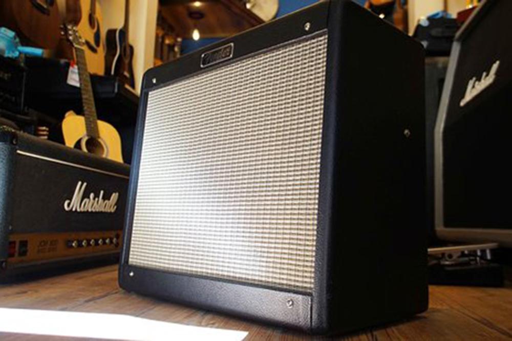
I get these on the bench constantly, and the complaint is always the same two sentences: it breaks up too early, and it sounds boxy. Both are true. Both are fixable for roughly the price of a set of strings.
The Blues Junior is a genuinely clever product. Fifteen watts, a 1×12, small enough to carry in one hand, loud enough to argue with a drummer, all-tube, and cheap. Fender sold a mountain of them and deserved to. But it looks like a blackface Fender and it does not sound like one, and once you have heard what it nearly does, it is hard to unhear.
What follows is a mod set I have done many times. It is not an attempt to turn a Blues Junior into a museum-correct Twin Reverb — that is not a thing you can do to an EL84 combo, and chasing it would throw away the practical little amp you actually own. It is about finesse: a cleaner front end, a tone stack that behaves the way your hands expect, and a power amp that breathes instead of barking.
Every value below comes off the Fender factory service diagram, so you can check my homework before you heat the iron.
The Short Version
- Input grid stopper: 10 kΩ → 33 kΩ. Takes the twitchiness out of the front end without darkening it.
- Remove the 100 pF cap across the volume pot. It is there to keep the amp bright turned down; on this amp it just makes it thin and prickly.
- Re-voice the tone stack to Twin values. The slope resistor and treble cap are already blackface; it is the bass and mid capacitors that are wrong — .022 µF where a Twin uses 0.1 µF and 0.047 µF.
- Remove the 1500 pF cap working against the 430 kΩ resistor after V2B. That pair is a low-pass at 247 Hz, and it is the single biggest cause of the amp's nasal, closed-in voice.
- Rework the negative feedback and drop the internal presence network. Old Fender philosophy: let the tone stack do the treble.
- Bias the EL84s cooler. More clean headroom, longer tube life, a smoother transition into breakup.
- Leave the coupling caps alone. Deliberately. That is what keeps the bass tight when you push it.
The Amp
On paper the Blues Junior is straightforward: three 12AX7s, a pair of EL84s in fixed bias push-pull (unusual for EL84s — most small EL84 amps are cathode-biased), spring reverb, master volume, and an 8 Ω speaker. Fender's own output test on the schematic specifies 15 W minimum, 10.95 V<sub>rms</sub> into 8 Ω, at 5 % THD. Note that 5 % — it is a much dirtier operating point than a hi-fi rating, which is a whole subject of its own.
Several specific choices steer it away from the mid-'60s blackface sound it resembles:
The tone stack is in the wrong place and has the wrong caps. In a classic blackface, the stack sits right after the first gain stage and ahead of the volume control. The Junior parks it later in the preamp — and, more importantly, uses capacitor values that emphasise the low mids rather than producing the familiar blackface scoop. I will put exact numbers on this below, because this is the mod that does the most work.
A treble bleed on the volume pot. A 100 pF capacitor bypasses highs around the pot so the amp stays bright when turned down. Reasonable in principle. On this circuit it makes the tone thin and prickly at exactly the volumes you gig at.
A low input grid stopper. 10 kΩ, which lets the first stage see everything your pickups can throw at it, and contributes to the amp feeling touchy and breaking up early.
A hidden low-pass in the middle of the preamp. More on this in Step 4. It is the one that surprises people.
A presence network wrapped around the feedback loop. Note there is no presence knob on the front panel — this is an internal, fixed network in the negative feedback path. It gives a useful bright edge in stock form and is not part of the blackface vocabulary at all.
EL84s run fairly hot. They compress and crunch sooner than the 6V6 or 6L6 pairs of the amps it is imitating.
The result is a very usable club amp that leans British-meets-tweed rather than the airy, piano-like clean of a Deluxe Reverb. Plenty of people love it exactly as it is. Others hear a great blackface tone stuck in there.
What I Was Going For
Three things, in order of importance:
- Clean headroom and predictable sensitivity. The amp should stay clean longer, track your picking dynamics, and take pedals without collapsing into fuzz at modest stage volume.
- Classic Fender balance. Less boxy low-mid, controlled bass, a gentle scoop, and a sweet top you dial in with the tone controls rather than one baked into the circuit.
- A more composed power amp. Cooler bias and a revised feedback network — blackface rather than hot-rodded combo, while staying tight in the low end.
And one non-goal, which matters as much: the coupling caps do not change. I want this amp to stay tight in the bass and to distort in a modern, controlled way, not to flub out when pushed. More on that at the end.
Careful — Read This First
A tube amplifier contains lethal voltages, and the Blues Junior is no exception just because it is small. Even after it is switched off and unplugged, the filter capacitors can hold enough energy to kill you.
If you are not already comfortable reading a schematic, discharging filter caps safely and working around high voltage, this is not the amp to learn on by trial and error. Find a competent tech; with the schematic in hand, every change here is half an hour's work for somebody who does it daily.
There is a second hazard specific to this amp: it is a PCB-based combo, and the board is not generous. Excessive heat, aggressive desoldering or leverage on a pad will lift traces. Use a decent iron, use solder wick rather than force, and do not work on it tired.
The Mods
Step 1 — Input grid stopper: 10 kΩ to 33 kΩ
Stock, the resistor between the input jack and the first grid is 10 kΩ, with a 1 MΩ pulldown to ground. Change the 10 kΩ to 33 kΩ.
That grid stopper forms a low-pass filter with the tube's own input capacitance — the Miller capacitance of the first stage, which for a 12AX7 in this configuration is on the order of 100 pF. Going from 10 kΩ to 33 kΩ moves that corner down, but it is still well above the guitar's range, so the amp does not get darker in any way you would describe as darker. What it does is round off the sharpest transients before they hit the grid.
The result under the fingers is an amp that feels controlled rather than twitchy, especially with hot pickups. That is exactly what you want if you are chasing blackface clarity instead of ragged break-up at the slightest provocation.
Step 2 — Remove the 100 pF treble bleed on the volume pot
The volume control is a 1 MΩ audio pot with a 130 kΩ taper resistor, and there is a 100 pF capacitor bridging it to keep the highs alive at low settings.
Take the cap out.
In theory it compensates for the natural darkening as you turn down. In practice, on this amp, it makes things brittle exactly where you spend your evening. Removing it:
- makes the volume taper feel progressive and natural, particularly between 1 and 3
- keeps the tone full and balanced at moderate loudness, instead of shrill
Because of the other changes here, the amp stays open and articulate without it. It simply stops going into ice-pick mode whenever you keep the volume civilised.
Step 3 — Re-voice the tone stack to Twin values
This is the mod that does the most, and the factory values explain exactly why.
The Blues Junior stack is a Fender-style stack. Its slope resistor is already 100 kΩ and its treble capacitor is already 250 pF — both identical to a blackface Twin. So the topology is right and two of the four critical values are right, which is why it nearly works.
What is wrong is the other two:
- Bass capacitor: .022 µF, where a Twin uses 0.1 µF
- Mid capacitor: .022 µF, where a Twin uses 0.047 µF
- Mid pot: 25 kΩ linear, where a Twin uses 10 kΩ audio
That bass cap is the headline. At roughly a fifth of the Twin's value, it moves the bass control's action up out of the actual bass and into the low mids — which is precisely the "boxy" quality everybody complains about. The amp is not lacking bass exactly; its bass control is operating in the wrong place.
Fit the Twin values and the stack behaves the way your hands already expect: set everything to 5 and you get a balanced, usable sound, and small moves on Bass or Treble produce proportionate results instead of wild swings.
Because we are also disengaging the presence network in Step 5, this stack becomes the amp's main high-frequency sculptor. That is the blackface philosophy — the EQ and the guitar decide the brightness, not a hidden circuit.
Step 4 — Remove the 1500 pF nose
Here is the one nobody expects, and the one where having the schematic in front of you pays off.
After the second gain stage's plate, the signal passes through a 430 kΩ resistor, and there is a 1500 pF capacitor shunting to ground at that node. Work out what those two do together:
That is a low-pass filter at 247 Hz, sitting in the middle of the preamp. Everything above the low bass is being progressively rolled off, right there in the gain structure, before it ever reaches the master volume.
That is where the amp's "nose" comes from. The stage is carrying a lot of lows and low mids while the upper mids and top are deliberately damped — so the amp sounds closed-in and mid-coloured, and then the presence network and the tone stack are left fighting a voicing decision that has already been baked in upstream.
I take that capacitor out entirely.
Doing so:
- lets the stage run wide-band for guitar purposes instead of arriving pre-tilted dark, which immediately makes the amp feel more open and honest
- moves the tonal decision-making to where it belongs — the tone stack and the feedback network — instead of a hidden low-pass plus a compensating presence circuit
Find it on your own board before you cut anything. This capacitor is C35 on the green-board revisions and C9 on the combined Fender service diagram, and on at least one PCB assembly Fender fits a jumper in that position instead of a capacitor. If yours has a jumper there, you have nothing to remove and this step is already done for you. Identify the part by tracing it from the 430 kΩ resistor, not by the silkscreen number.
If you want to address harshness or stability in an amp like this, grid stoppers, coupling caps and feedback tuning are the right tools. A broad low-pass in the middle of the preamp is not.
Step 5 — Negative feedback and the presence network
Classic blackface amps use a simple negative feedback loop around the power amp to control gain and tighten the response, generally with no separate presence control on the front panel. The Blues Junior takes a different route.
Its feedback comes back from the output transformer secondary through a 75 kΩ resistor into the phase inverter, and the shunt network at the injection point includes a 0.1 µF capacitor with a 7.5 kΩ resistor alongside a 4.7 kΩ resistor. That RC branch has its corner at:
So above about 212 Hz — which is to say, across essentially the whole guitar range — that branch changes the shunt impedance and reduces the amount of feedback. Less feedback means more gain and less damping up top. That is a fixed, internal presence circuit, and it is a broad one rather than a subtle peak.
It is also worth noting the topology is not the blackface one. A Deluxe Reverb injects feedback into the phase inverter's cathode tail through a small resistor — 820 Ω into a 100 Ω tail is the classic arrangement. The Junior injects into a grid through a large one. So "change the feedback resistor to Fender values" is not a like-for-like swap; the two circuits want different numbers because they are different injection points.
With the preamp now running open rather than nasally filtered, that presence network is redundant at best and counterproductive at worst. Revise the feedback values for the response you want and take the presence branch out of the equation. The power amp then:
- responds like an old Fender — firm without being sterile, articulate without being hyped
- keeps a consistent top-end character across volume settings, instead of shifting as the loop's behaviour changes
Brightness is now governed by the tone stack, the speaker and the guitar. Which is how the classics do it.
Step 6 — Bias the EL84s cooler
The Junior sets its EL84 bias with a fixed resistive divider — there is no trimmer from the factory — and the control grids sit at roughly −10.6 V. It runs them fairly hot.
The usual mod is to fit a trim pot so you can dial idle current exactly, and that is a perfectly good idea. For this build I keep it conceptually fixed-bias and simply swap the bias-set resistor for a value that runs the tubes cooler.
An EL84's maximum plate dissipation is 12 W, which is a small budget — there is much less room for error than with a 6L6. Lowering the idle current:
- increases clean headroom, pushing the onset of power-tube distortion further up the dial
- reduces harshness when the amp is played loud, giving a smoother, more controlled transition into breakup
- improves tube life, since you are not running them at the edge all night
You still get the EL84 crunch when you crank it or hit it with a boost. It is just more composed and less spiky — a better partner for the blackface-voiced preamp you have just built.
If you are setting bias by measurement rather than by resistor value, the output-transformer resistance method is the way I do it, and Bias Bench will do the arithmetic.
What We Deliberately Leave Alone
The coupling capacitors, and this is a real decision rather than an omission.
In a lot of vintage-style mod recipes the coupling caps get reduced to thin the low end and stop the amp flubbing when it distorts. Here they stay exactly as Fender fitted them, because the goal is not a brittle, underfed vintage clone. What I want out of this amp is:
- tight, modern bass that holds together under distortion, which matters for contemporary playing and for higher-gain pedal work
- a preamp and power amp that stay articulate as they overdrive rather than collapsing into mush
The Twin-style stack, the removed 1500 pF nose and the cooler EL84s give you the cleaner, more Fendery front end. The original coupling caps keep the tightness a lot of players actually rely on. Changing both would be changing two things at once and getting neither.
If it comes out too bright
With the nose removed and the preamp opened up, the amp is notably more transparent. For this style of mod that is the point — you shape brightness with the guitar and the tone controls rather than fighting a dark circuit. But if it is too much for your ears or your speaker:
Put the shunt capacitor back at a much smaller value. Against that same 430 kΩ, the arithmetic tells you exactly what you will get:
- 220 pF puts the corner at about 1.7 kHz — a gentle top-end tame
- 100 pF puts it at about 3.7 kHz — barely there, just taking the edge off
Either is a completely different proposition from the stock 1500 pF at 247 Hz. You are trimming the top, not re-voicing the whole amp.
A small shunt capacitor elsewhere in the later preamp will do something similar. I have used a 500 pF across a plate resistor further down the chain to smooth out any remaining ice-pick. Be aware that the designators differ between board revisions, so trace the part on your own amp rather than trusting a number from an article — including this one.
I would leave it out entirely and rely on the tone stack and the guitar's tone knob. In a band mix a little extra air is usually your friend rather than your enemy.
How It Turned Out

On paper these are resistor and capacitor values. In the room they change what the amp is.
Cleans. The neck pickup stops collapsing into woolly haze. You get a piano-like low end and clear, chiming mids that genuinely recall a good blackface Fender — delivered, improbably, by an EL84 combo.
Edge of breakup. You can now park the amp right at the verge. Dig in and it grits up; back off and it cleans up. Much like a well-set Deluxe Reverb, which is the entire point of the exercise.
Pedals. Overdrives, boosts and delays start behaving like extensions of the amp rather than band-aids for it. The tighter low end and cooler bias keep things articulate, and the Twin-style EQ and open preamp mean your pedals are not fighting a baked-in mid hump and a brittle presence peak.
It still sounds like a Blues Junior — compact, agile, immediate. Its manners are just firmly in blackface territory now.
For anybody who has ever liked what a Blues Junior almost does, this is the sweet spot: a practical, giggable combo that finally lives up to its looks.
Try It Yourself
Before you order a single capacitor, go and see the tone stack change in Tone Stack Lab. Set up the Blues Junior values — 100 kΩ slope, 250 pF treble, .022 µF bass, .022 µF mid — and look at the curve. Then change the bass cap to 0.1 µF and the mid cap to 0.047 µF and watch the whole low end unfold downward while the mid hump flattens out. That single picture is most of this article, and it costs nothing to look at.
Then do the same for the power amp end in Feedback Lab: the difference between a feedback loop with a presence branch and one without is exactly the kind of thing that is much easier to see than to describe.
Sources
- All stock component values are read from the Fender Musical Instruments Blues Junior combined service diagram, drawing 0057275000 Rev D: the 10 kΩ input grid stopper, the 1 MΩ / 130 kΩ volume pot arrangement with its 100 pF bleed, the 100 kΩ slope and 250 pF / .022 µF / .022 µF tone stack, the 430 kΩ + 1500 pF network, the 75 kΩ feedback resistor with its 7.5 kΩ / 0.1 µF / 4.7 kΩ shunt, the 220 kΩ EL84 grid leaks, the 1.5 kΩ grid stoppers and 100 Ω screen resistors, and the −10.6 V bias node.
- The 15 W / 10.95 V<sub>rms</sub> / 8 Ω / 5 % THD output test specification is printed on that same schematic.
- Blackface Twin tone stack values (0.1 µF bass, 0.047 µF mid, 10 kΩ audio mid pot) are from the Fender AB763 circuit.
- The 820 Ω / 100 Ω blackface feedback arrangement is the AB763 Deluxe Reverb's, given for contrast only — it is a cathode-injection topology and does not transplant directly.
- EL84 maximum plate dissipation of 12 W is the datasheet figure.
- Designators vary between board revisions. The nose capacitor is C35 on green-board layouts and C9 on the combined diagram. Trace parts on your own amp; do not cut by silkscreen number.