Tech pages · Repair · Guitar Amps · Electronics
The Five Faults Behind Most Amp Repairs
The internet's list of common amp faults was written for amps built in 1965. What actually walks through the door now is bad assembly and bad repairs, not bad components.
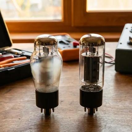
Search for common tube amp faults and you will get the same list every time. Tubes first. Then filter capacitors. Then something vague about old resistors drifting. It is a good list. It is also about sixty years out of date, and following it is why people arrive at my bench having already bought two sets of tubes and a recap kit for an amp that never needed either.
That list was written for amps built in the 1960s and 70s, when the components genuinely were the weak link. Electrolytics dried out, carbon comps drifted, and the assembly was done by people who hand-wired amps all day, every day, and were extremely good at it.
Both halves of that have reversed. The components in a modern amp are better than anything Leo Fender could buy — more consistent, better sealed, tighter tolerances, longer rated life. The assembly is a mass-production PCB process built to a cost, usually a long way from where the brand name is printed. So the failure distribution moved. What I pull out of amps now is mostly not a worn-out part. It is a connection that was never properly made in the first place, or damage done by whoever was in there before me.
The Short Version
- The most common fault I find is not a component at all. It is a solder joint that left the factory without ever properly wetting — a mass-production yield problem, not an ageing problem.
- Second is damage done by the last person who worked on it. Lifted pads, cooked traces, and parts shotgunned in one after another by somebody who never localised the fault.
- Tubes fail, but they get blamed far more often than they are guilty. A marginal tube-socket contact produces the identical symptom, and swapping the tube "fixes" it by reseating the socket. There is a one-minute test that separates the two, and almost nobody does it.
- Filter capacitors are not the liability they were. An F&T Type A high-voltage axial is rated for roughly 35,000 hours at 65 °C. At ten hours a week that is sixty-seven years. Caps wear out on amps that are used, not on amps that are old.
- Jacks and switches have always failed and always will — they are mechanical parts in an electronic box, and PCB-mounted ones made it worse, not better.
- Bias drift is rare on a modern amp. Where it is real, it is old single-turn trimmers, and a multi-turn replacement fixes it permanently for the price of a coffee.
What Everyone Gets Wrong
The instinct when an amp misbehaves is to reach for a part. Something must be worn out, so the job is to work out which thing and replace it. That instinct is a hangover from an era when it was correct.
It also has a commercial tailwind, because there is a whole industry selling you the part. Nobody sells "your solder joint is fine, it just needs reflowing." So the folklore keeps pointing at tubes and capacitors, and the two faults that actually dominate my bench — bad factory soldering and bad previous repairs — barely appear in it at all, because neither of them has a product attached.
Here is the same list, in the order things actually walk through the door.
Fault One: The Joints That Left the Factory That Way
A cold joint is solder that never got hot enough to alloy with the pad and the lead. It sits there as a mechanical blob rather than a metallurgical bond. It usually looks dull and grainy instead of shiny and concave, and often has a fine dark ring where the lead enters. A cracked joint is a different history with the same result — it was a good joint once and years of heating up and cooling down opened it. On the bench they behave identically, so I will treat them together.
Why so many? Because wave and reflow soldering are statistical processes with a yield, not guarantees. A big tube-socket pin or a transformer lug next to a small pad steals heat from the joint and it never reaches temperature. Boards come off the line fast, get hand-touched where the machine did not take, and there is a cost target on every one of those steps. Multiply that by a factory building thousands of chassis, and a small percentage rate becomes a lot of amps.
They cluster where you would expect: tube sockets above all, because that is the maximum of thermal cycling and mechanical stress in the whole amp; then power resistors, filter cap terminals, and the lugs where board meets panel hardware.
The symptom is the tell, and the tell is intermittency. It works, then it doesn't, and it changes with temperature, with vibration, and sometimes with which way the chassis is sitting. Crackle. Dropouts. A channel that switches on its own. The owner cannot reproduce it on demand, which is why so many of these get sent back from a shop marked "no fault found" — because the tech could not reproduce it either.
On the bench: a PRS MT15 came to me as a noise complaint. Before it reached me the owner had already swapped the preamp tubes, replaced a ceramic capacitor with a film type on the theory that the ceramic was piezoelectric, and replaced every resistor in the network around it. The noise was still there. A tiny burst of freeze spray on that node produced loud crackling immediately. It was never any of the parts he bought — it was a marginal joint or trace at the node they all shared.
That case is worth sitting with, because it is the whole article in miniature. Three plausible component theories, three parts bought, and the fault was in the connection between them.
To find one: with the amp powered and warm, prod each joint and lead in the suspect area with an insulated tool — a wooden chopstick is the traditional weapon — and listen. Mechanical flex reproducing the crackle is your answer. Freeze spray works too, but use the straw nozzle and tiny bursts on one joint at a time, because overspray hits three neighbours and misattributes the fault to whatever the nozzle happened to be pointing at. And run the control: if warming the same spot with a hair dryer also triggers it, you have a genuine thermally-sensitive joint rather than static noise from the aerosol itself.
To fix one properly, add flux and fresh solder and reflow both sides of a plated through-hole. Simply re-melting the existing joint tends to re-make the same bad joint, because the reason it failed the first time — contamination, oxide, not enough heat — is still there.
Fault Two: What the Last Person Did to It
Fault One creates Fault Two. An intermittent that nobody can localise invites the shotgun: replace the tube, replace the cap, replace the resistors, replace the thing next to it. Each of those is another two heat cycles on a pad that was built to a cost, and cheap boards do not have much to give.
What that leaves behind: lifted pads where the copper has let go of the laminate, torn traces, vias drilled through by a desoldering pump, solder bridges, and parts with their leads cut so short they cannot be removed again without taking the pad with them. Plus the ordinary substitution errors — wrong value, wrong voltage rating, an electrolytic in backwards, a resistor lying flush against the board where the factory deliberately stood it proud.
That last one is not hypothetical. It is exactly the mechanism behind the Hot Rod Deluxe's famous channel-switching faults: Fender mounted the large dropping resistors flat against a low-quality PCB, and a resistor dropping 100 V at 20 mA is dissipating 2 W continuously with nowhere to put it but the board underneath. The laminate discolours, the traces degrade, and you get crackle and phantom channel switches. I wrote up the fix in my Hot Rod Deluxe article — chassis-mount the resistors so the aluminium takes the heat. If you are replacing parts on a board that already runs hot, at minimum stand them off it.
You can usually see a previous visit before you measure anything: solder of a different colour or finish to the factory's, flux residue where the production line left none, one component sitting at a different height to its neighbours, hand-soldered joints on an otherwise wave-soldered board. When I see that, I revise the estimate upward, because an untouched broken amp is almost always cheaper and faster to fix than a "repaired" one. In the second case I am fixing two problems, and one of them has destroyed the evidence for the other.
So, to anyone learning this on their own gear — and I include my younger self here, because I have made every one of these mistakes: if you cannot find the fault, stop. Do not keep swapping parts to see what happens. Every part you change makes the board a little worse, costs money, and removes a piece of evidence. Localise the fault to a node first, then act on that node. A meter, a chopstick and patience find more faults than a parts order does.
Fault Three: Tubes — Real, and Badly Over-Diagnosed
Tubes do fail, and they fail in at least four genuinely different ways that do not sound alike.
- Microphonics — the tube rings, pings or howls when you tap the chassis or when the cabinet gets loud enough to shake it. Something inside is mechanically loose or resonant. Preamp tubes, especially the first gain stage, because that is where the smallest disturbance gets the most amplification downstream.
- Gas — a tube that has lost some vacuum shows a blue-purple glow following the internal structure (distinct from the harmless general blue fluorescence some tubes show against the glass), runs unstable, and can draw enough current to take other parts with it.
- Weak emission — undramatic. Less output, less headroom, an odd unbalanced feel in a push-pull pair. Ordinary end of life, and the usual reason an amp that used to sound alive now sounds flat with nothing actually broken.
- A short — the loud one. Blows a fuse the instant you power up, or dumps current through things not built for it. If a fuse goes the moment the amp is switched on, suspect a shorted power tube before anything else.
All of that is true. Here is what the fault lists leave out: a loose or oxidised tube socket contact produces the same symptoms. Intermittent grid noise from a marginal socket pin presents exactly like microphonics. A poor contact on one side of a push-pull pair looks exactly like an unbalanced tube.
And now the trap. You swap the tube, the noise goes away, and the tube gets the blame — except that pulling a tube and pushing a new one in scrapes and reseats every pin in that socket. You may have fixed a contact, not replaced a bad tube. The amp comes back in four months and the owner buys another set.
Rule of thumb: when a tube swap fixes a fault, put the old tube back in before you close it up. Still fixed? Then the tube was never the problem — you cleaned a socket. That is a one-minute test and it is the single highest-value habit on this list.
Two practical notes. The tap test is a real diagnostic, and PRS's own MT15 manual documents it: with the amp powered, tap each tube lightly with a pencil. A healthy tube gives a faint metallic click; a microphonic one rings loudly through the speaker. And preamp tube swaps need no rebias — power tube swaps do, which is the one place bias genuinely matters.
Fault Four: Filter Capacitors Are Better Than Their Reputation
Myth: the amp is over twenty years old, so it needs a recap.
Verdict: on hours, sometimes. On calendar age alone, for a modern amp, almost never — and the manufacturer's own datasheet is what says so.
The number people half-remember is that a filter cap is good for so many thousands of hours. That is real, but it is routinely misread. An endurance figure is powered operating hours, at the capacitor's rated temperature, under full rated ripple current. It is not shelf life and it is not calendar age, and those are wildly different things.
Take the actual part that goes into these amps. F&T Type A axials, the ones sitting in half the retubed Marshalls in the country. The datasheet rates the high-voltage versions (above 100 V, so all the 350/450/500 V parts) at −40 °C to +85 °C, and publishes a useful-life diagram against ambient temperature and ripple current. Read at full rated ripple, it goes roughly like this:
| Ambient at the can | Useful life | Player, 10 h/week | Backline amp, 2,500 h/year |
|---|---|---|---|
| 85 °C — the rating | ≈5,000 h | ≈10 years | ≈2 years |
| ≈65 °C | ≈35,000 h | ≈67 years | ≈14 years |
| ≈45 °C | ≈140,000 h | ≈270 years | ≈56 years |
Read those two right-hand columns against each other, because that is the whole point. The player who has the amp switched on ten hours a week — which is a lot of playing — is doing 520 hours a year, and never gets near the rating. The rehearsal room, the backline amp, the studio amp that is powered eight hours a day six days a week is doing about 2,500 hours a year, and it eats the same rating in two to fourteen years depending on how hot it sits. That is what "used a lot" means, quantitatively, and that is the amp whose caps are genuinely worn out.
Two honesty notes on those numbers, because they are read off a log chart and extrapolated. The temperatures in that table are my reading of the diagram and are worth ±5 °C. And the underlying rule — life roughly doubles for every 10 °C below the rating — is an approximation the manufacturers themselves fence in: Nippon Chemi-Con's own lifetime note floors the calculation at 40 °C and caps the estimated life at fifteen years no matter what the arithmetic produces. So do not read "270 years" as a promise. Read it as: for a normally-used amp, powered hours are simply not the thing that will kill the capacitor.
What does still get them: heat position, because a can bolted next to the power tubes lives at a very different temperature from the room; a genuinely bad part, which happens; and decades of storage, where the seal diffuses and the electrolyte dries out with the amp switched off the whole time. Calendar age is not nothing. It is just not the first thing to suspect, and it is nowhere near the first thing to spend money on.
When they do fail, the symptoms are worth knowing. Hum at 100 or 120 Hz — mains frequency doubled by full-wave rectification — as the cap loses its ability to smooth the rail. Sag and flabby bass under load, because it cannot hold the rail up when the power section asks for a burst of current; this one gets misdiagnosed as a bias problem or a speaker problem constantly. And rarely, a short, which can take a rectifier or a dropping resistor with it.
And one loop back to Fault One: a capacitor that measures perfectly can still have a bad joint at its terminal, and it will produce hum and crackle exactly like a failing cap. Check the connection before you condemn the part. That was literally the MT15.
Fault Five: Jacks and Switches
The unglamorous one, and the one thing on this list that modern manufacturing genuinely has not improved.
Input jacks, speaker jacks, footswitch jacks, channel switches — these are mechanical parts sitting in an electronic circuit, and they fail mechanically. Contacts oxidise. Springs lose tension. Switch wipers wear through their plating. This was true in 1965 and it is true now.
What did change, and not for the better: on a hand-wired amp the jack is bolted to the chassis and connected with flexible wire, so when somebody trips over a cable the force goes into the chassis. On a PCB-mounted jack, that same force goes straight into solder joints and traces. Which means Fault Five, on a modern amp, has a habit of turning into Fault One.
The signature is mechanical, not thermal: crackle and dropouts that change when you wiggle the cable at the jack or work the switch, and that do not care whether the amp is warm. That is the diagnostic that separates it from a cold joint elsewhere, which responds to temperature and to prodding somewhere the cable is not.
Clean first — a proper contact cleaner and a dozen actuations resolves a large share of these, and it is the highest fix-to-effort ratio on this whole list. But be honest about when cleaning is a stall: if the contact is physically worn or the spring has lost tension, cleaning buys you a few months and the amp comes back. Replace it.
The One That Gets Blamed and Usually Isn't: Bias Drift
Bias drift deserves its own section mostly so I can talk it down, because it turns up in every one of those internet fault lists and it is not what is wrong with your amp.
On a modern fixed-bias amp, the bias supply is a simple, robust circuit and modern sealed trimmers hold their setting. I do not see meaningful drift on these.
Where it is genuinely real is older amps with old open-frame trimmers. Those drift with age and humidity, the wiper oxidises, and the setting moves. It is made worse by the fact that a single-turn trimmer crams the entire adjustment range into 270 degrees of rotation, so a small knock or a slightly oxidised wiper translates into a meaningful change in idle current.
The fix is cheap and permanent: replace it with a quality sealed multi-turn trimmer. Same resistance range spread over roughly twenty turns, so the same physical disturbance moves the bias by a twentieth as much — and as a bonus you can finally set it precisely instead of chasing it past the value in both directions.
What people usually mean when they say bias drift is "the amp isn't what it used to be," and that is normally ageing tubes doing exactly what Fault Three describes, or a joint doing what Fault One describes. The genuine reason to check bias is not that it drifted — it is that you changed the power tubes, and that is not optional.
What This Means on the Bench
Careful: everything below that involves an open chassis is around B+ rails of 400–550 V, and the filter caps hold that voltage after the amp is unplugged. Discharge them and verify with a meter before anything goes near the board. The wiggle test at the jack and the tube-reseat test are safe to do; nothing else here is, unless you already know it is.
Localise before you buy. The cheapest fault to fix is the one you found before ordering anything. A meter and a chopstick beat a parts order.
Put the old tube back. One minute, and it tells you whether you fixed a tube or a socket.
If you cannot reproduce the fault, reproduce the conditions. Run the amp until it is properly warm. Tap the chassis. Wiggle every cable. Tilt it the way it sits on stage. Faults One and Five are conditional, not constant, and "I can't make it fail right now" is not the same as "nothing is wrong" — that is how a real fault gets sent back out the door.
Look for who was here before you. Mismatched solder, stray flux, a part at the wrong height. It changes what the job is.
Suspect the connection before the component. That is the one sentence version of this entire article.
Try It Yourself
The one fault on this list you can put a real number on at home is the last one, and it is worth doing whether or not anything sounds wrong — particularly after a tube change. How to bias a fixed-bias push-pull power amp walks through the measurement safely, and Bias Bench does the arithmetic once you have the readings: put in your plate voltage and measured idle current and it will show you where you are sitting against the tube's dissipation limit, so you can tell an amp that has genuinely moved from one that is exactly where it should be.
If you want to see Fault Two as a finished job rather than a warning, the Hot Rod Deluxe article documents the resistor-and-board fix end to end, and Blues Deluxe Mods covers the sibling amp that looks like it should take the same treatment and does not.
Sources
- Capacitor life figures are read from the FTCAP Type A axial aluminium electrolytic datasheet, section 2.3.1 "Useful Life Type A", the diagram for rated voltages above 100 V, taken at full rated ripple current. The temperature range for those parts (−40 °C to +85 °C) is from the same datasheet's quick-reference table. Reading a log-scaled diagram by eye is worth about ±5 °C, and I have said so in the text rather than implying precision I do not have.
- The doubling-per-10 °C lifetime rule, its 40 °C floor and its fifteen-year cap are from Nippon Chemi-Con's published lifetime estimation note for aluminium electrolytic capacitors. Their own document states that the rule does not hold across all temperature ranges, especially for parts rated 105 °C and above.
- The tube tap test and the preamp-versus-power-tube rebias rule are documented in the PRS MT15 owner's manual (LIT-AMP-MAN-MT15 REV B), which treats microphonics as a routine tube failure mode rather than a fault bulletin.
- The MT15 case in Fault One is my own bench work, including the freeze-spray localisation and the sequence of parts the owner had already replaced. I searched the PRS forums, The Gear Page and Reddit for anyone reporting the same fault on the same node and found nothing — so treat it as a unit-specific soldering defect, not a model-wide design pattern.
- The Hot Rod Deluxe dropping-resistor mechanism (R78, R79 and R97 against the board) is from my own work on those amps and is documented with photographs in that article.
- The ordering of these five is my own bench experience, not a survey. It is what walks through my door, weighted by what I see, and a shop that mostly handles vintage point-to-point amps would rank them differently — with much more of Fault Four and much less of Fault One. That difference is the whole argument of this article, so it is worth stating plainly rather than dressing my sample up as a statistic.
The short version of all of this is that we inherited a fault list from an era when parts were the weak link, and we kept using it after the parts got good. Check the connection before you condemn the component, and put the old tube back before you believe the new one fixed anything.
Until next time, happy chugin'.