Tech pages · Repair · Guitar Amps · Electronics
Reading an Amp Schematic
Every mod article on this site says 'look at the schematic.' Here are the twenty symbols, drawn, and the tracing method that makes that instruction usable.
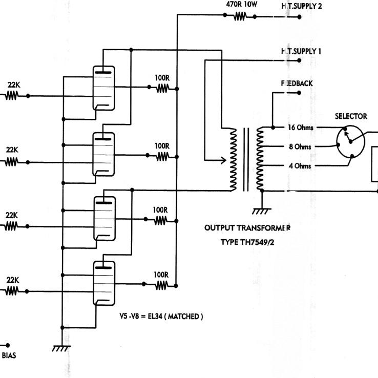
Every mod article I've written tells you to go look at the schematic. The Grinder, the Hot Rod Deluxe, the Blues Junior — all of them assume you can open a PDF full of lines and symbols and actually extract something useful from it. That's a real skill, and nobody on this site has ever taught it. Let's fix that.
This isn't a electronics theory course. It's the specific, narrow skill of reading a guitar amp schematic — which uses a small, repeating vocabulary of symbols and follows a predictable shape, once you know what to look for.
The Short Version
- Guitar amp schematics use about twenty symbols, repeated constantly. Learn those twenty and you can read almost any factory drawing you'll ever encounter.
- Signal flows left to right, mostly, from the input jacks to the speaker. Following that flow, stage by stage, is the single most useful habit you can build.
- Every amp has four supply nodes you should be able to point to on any schematic: the high-voltage plate supply (B+), the negative bias supply, the tube heater supply, and ground — and ground is not one wire, it's a whole network worth understanding.
- Component values on the page are a starting point, not gospel. Real amps deviate from their own factory drawings due to production changes, and designators can differ between board revisions of "the same" amp — a lesson the Blues Junior and Blues Deluxe articles both had to flag explicitly.
- Tracing a signal path is a specific, learnable procedure: start at the input, follow the wire to the first active device, identify what kind of stage it is, note what comes out, repeat.
The Symbol Vocabulary
Here's the list. If you can recognize these on sight, you can read the great majority of a typical guitar amp schematic without hesitation.
Passive components

- Resistor. Two conventions, same part. The zigzag is the US drawing style you will see on Fender and Marshall sheets; the plain box is IEC, and it is what most modern and European-drawn schematics use. Values are printed beside the symbol, abbreviated:
kfor thousand,Mfor million, a bare number for ohms. - Capacitor. The curved plate means polarised — an electrolytic, where fitting it backwards is a real failure and sometimes a loud one. Values are in µF or pF, and this is where the genuine trap lives: a "22" with no unit could be either, and reading µF for pF is a factor of a million.
- Potentiometer. A resistor with a third terminal — the wiper — that slides along the track. Two ends and a tap.
- Inductor. A coiled line. Rare outside power supplies, wah circuits, and the windings of a transformer.
Active devices

- Vacuum tube. The circle is the glass envelope. Inside it, from the top down: the plate (or anode), a flat bar; the grid, a dashed line standing for the wire mesh; and the cathode, which the heater — the little filament V — warms so it can emit at all. The heater carries no signal and is often drawn on a separate sheet entirely.
- Triode versus pentode. Count the dashed lines. One grid is a triode, which is every half of every 12AX7 in your preamp. Three is a pentode: control, screen and suppressor, in that order coming away from the cathode. Draw them in any other order and it is a different tube.
- Diode. Conducts the way the triangle points. The bar is the cathode.
- Transistor. Three leads and an arrow. The arrow sits on the emitter, and if it points away from the base it is an NPN.
Connections and structure

- Ground. Bars shrinking in width. Every ground symbol on the page is the same electrical node — they do not need a wire drawn between them. Miss this and the circuit looks far more disconnected than it is.
- The junction dot. A dot means connected. Wires crossing with no dot are not connected; they just happen to cross on the page. This one distinction causes more misreadings than anything else on a schematic — when a drawing seems to contradict what you are hearing, check the dots before you check anything else.
- Node label. A labelled arrow — "B+", or a letter code — saying the wire continues elsewhere on the sheet, or on another sheet. Factory drawings are full of these.
- Switch. Drawn in one position; the lever moves. Multi-position switches get extra contacts.
- Test point. A small circle with a voltage beside it, telling you what a healthy amp should read right there. The Blues Junior and Blues Deluxe schematics on this site are covered in them, and they are the most useful thing on a drawing when you have a meter in your hand.
Transformers

- Transformer. Two windings either side of a pair of lines standing for the iron core. Both transformers in an amp are drawn the same way — what distinguishes them is what they connect to.
- The power transformer is at the front of the supply: one primary from the mains, then a secondary for every rail the amp needs — a centre-tapped high-voltage winding for B+, and a 6.3 V winding for the heaters.
- The output transformer is at the back: a centre-tapped primary fed from B+ with a power tube plate on each end, and a secondary whose load is the speaker itself. That centre tap is worth finding on any drawing, because it is where the negative feedback loop is taken from.
That's the whole vocabulary. Everything else on a typical schematic is combinations and repetitions of these twenty-odd symbols.
The Four Supply Nodes
Before tracing any signal, find these four things on the page. Every functioning tube amp has all four, and locating them first gives you a map to navigate the rest of the drawing.
B+ (high voltage plate supply). Usually labeled explicitly as "B+" somewhere, often with a voltage value nearby (300–500+ V is typical). This is what actually powers the amplification — tube plates connect to it, generally through a resistor or the primary winding of the output transformer. Trace B+ through the schematic and you'll find it branching out to feed every gain stage.
Negative bias supply. In a fixed-bias amp, look for a separate small supply, often drawn near the power transformer, producing a negative voltage relative to ground — this feeds the power tube grids through large-value grid-leak resistors. If you can't find one, the amp is likely cathode-biased instead — see cathode bias vs fixed bias for the difference, and look instead for a cathode resistor on the power tubes with no separate negative supply feeding their grids.
Heater supply. A low-voltage AC (typically 6.3V) supply feeding every tube's heater/filament, drawn separately from the high-voltage rails, usually near the power transformer with its own dedicated winding. This just heats the tube's cathode so it can emit electrons — it carries no audio signal and rarely needs troubleshooting attention beyond confirming it's present.
Ground. Not literally one wire — a whole network of connections, all electrically the same node, drawn as separate ground symbols scattered across the page for clarity. On a real amp, ground is usually also tied to the chassis itself at one or more specific points. Understanding that every ground symbol on the page is the same electrical point, without a drawn wire needing to connect them, is essential to reading the drawing correctly — miss this and the schematic looks far more disconnected than the actual circuit is.
How to Trace a Signal Path
This is the actual procedure, and it's the same one used, explicitly or implicitly, in every mod article on this site. Here is one gain stage with the whole thing marked on it — the five numbered steps below are the five numbers on the drawing.

- Start at an input jack. Follow the wire from the jack tip connection.
- Find the first active device it reaches — almost always a tube grid, in a guitar amp preamp. That's your first gain stage.
- Identify the stage type. Is the cathode grounded directly, or through a resistor (bypassed with a capacitor, or not)? Is there a grid-leak resistor to ground or to a bias supply? These details tell you whether it's a simple common-cathode gain stage, a cathode follower (look for the output taken from the cathode rather than the plate — this is exactly the Grinder mod's whole subject), or something else.
- Follow the output — typically from the plate, through a coupling capacitor (which blocks DC while passing the audio signal) — to wherever it goes next: another gain stage, a tone stack, a volume control.
- Repeat at each stage until you reach the power section: the phase inverter (splitting the signal into two out-of-phase halves for a push-pull output stage), then the power tubes themselves, then the output transformer, then the speaker jack.
- Note anything that branches off the main path — negative feedback returning from a speaker-jack tap back to the phase inverter (the entire subject of what the presence knob really does), reverb sends and returns, effects loops. These are side paths off the main signal chain, not part of the primary left-to-right flow, and recognizing them as branches rather than getting lost trying to fit them into the main sequence is a real skill in itself.
Do this once, slowly, on an amp you already understand reasonably well by ear, and the pattern-matching starts to click. Do it on a genuinely unfamiliar circuit and you'll find yourself able to answer real questions — "where would I inject a boost," "which capacitor sets this stage's bass rolloff," "is this cathode follower buffering the tone stack or not" — just from the drawing, before you've touched a single component.
What This Means on the Bench
Trust test points over your assumptions. If a schematic gives you a voltage at a labeled point, measure it on the real amp before assuming the circuit matches the drawing exactly — production amps deviate from their own schematics more often than people expect.
Designators are not universal even within "the same" amp model. The Hot Rod Deluxe article and the Blues Deluxe article both had to flag this explicitly — component numbering can differ between board revisions, so always confirm you're looking at the right drawing for your specific amp before cutting anything.
When a schematic seems to contradict what you're hearing, check the dots first. A misread junction — assuming two crossing wires are connected when they're not, or vice versa — is one of the single most common ways people misread a circuit's actual topology, and it's an easy thing to double-check once you know to look for it.
Practice on an amp whose behavior you already know. Reading a schematic cold, with no reference point for what the circuit is supposed to sound or feel like, is much harder than reading one for gear you've actually played and can cross-check your understanding against.
Try It Yourself
Tone Stack Lab draws a live schematic alongside every preset — watching the on-screen circuit update as you turn the controls is a genuinely good way to connect the static symbols on a page to what they're actually doing electrically. Load a preset, move the Bass and Treble controls, and watch which parts of the drawn circuit the wiper arrows move through.
Once you can read a schematic, every mod article on this site becomes something you can verify rather than just trust — the Grinder, the Hot Rod Deluxe, and the Blues Junior all include the schematic fragments that back up every claim made in the text.
Sources
- The symbol conventions described here follow standard US-convention tube-amp schematic drawing practice, consistent with Fender and Marshall factory drawings referenced throughout this site's other articles.
- The signal-tracing procedure reflects the author's own working method, developed through repair and mod work rather than derived from a single textbook source.
- The symbol drawings are mine, drawn as vector art rather than photographed from any one factory sheet. They deliberately use the same geometry and stroke weights as the live schematic inside Tone Stack Lab, so the symbols you learn here are the symbols you then see moving in the tool. Source files are in the site repository and can be corrected if I have drawn anything wrong — tell me if I have.